|
|
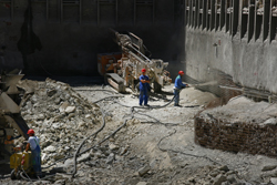
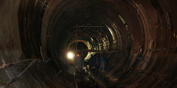
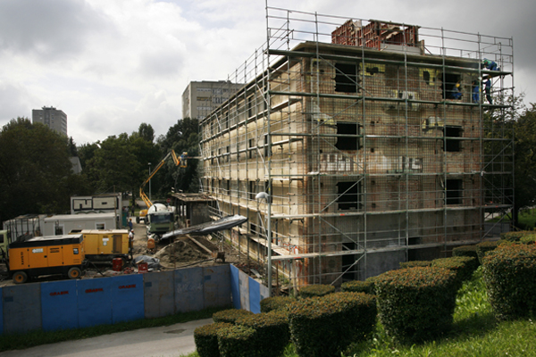
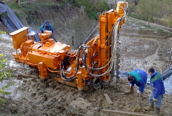
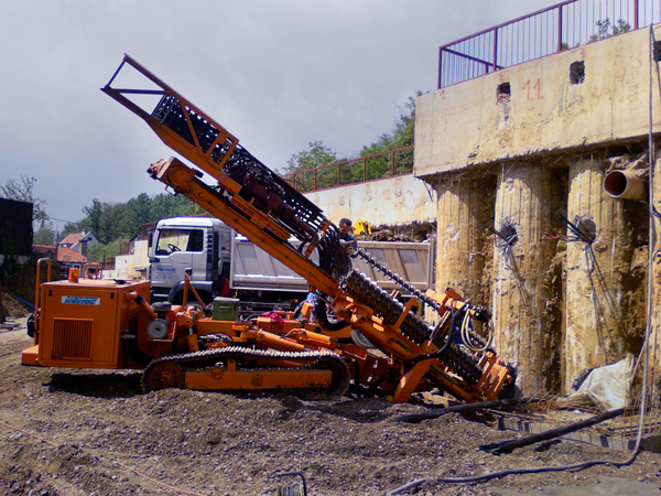
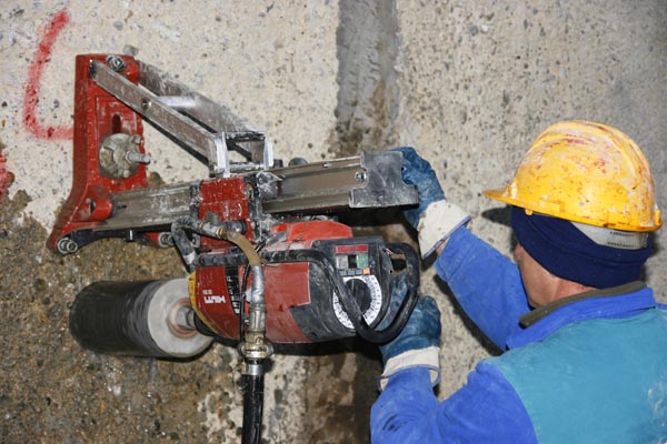
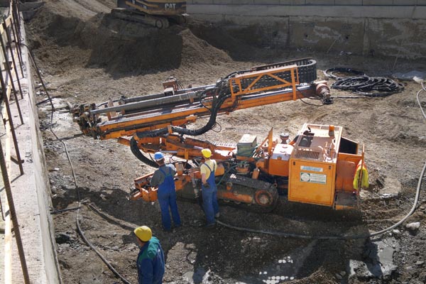
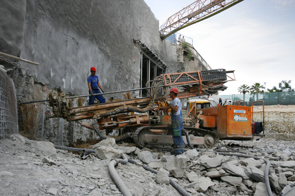
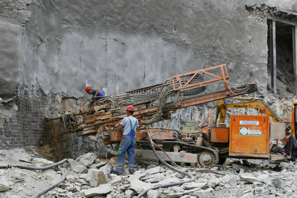
Grouting is a technical procedure used to improve mechanical capacities, reduce water permeability, and achieve a close contact between the object and field. The process is done by denting a certain type of suspension grouts, in liquid form, into a rock mass where they harden between aggregate pore spaces or other pores they are dented in. As a restoration measure, grouting ensures the structural integrity, longevity and full functionality of the building (for example, it prevents loss of content from pipelines, tanks and silos, while at the same time eliminating the possibility of damage to the installations, equipment and inventory caused by rainfall or groundwater leakage). In practice, the grouting of rock masses is done to enhance the mechanical properties of the rocks. By using contact grouting, a better connection between the object and rock mass is gained. With hydrotechnical tunnels and shafts under pressure contact grouting is used only when the rock mass has to be under internal hydrostatic pressure, and the lining only has to ensure the designed shape of the tunnel opening.
Geotehnika-Konsolidacija d.o.o. has extensive experience in carrying out repairs to facilities of hydropower plants, and in constructing and building the same objects when constructing curtain injections.
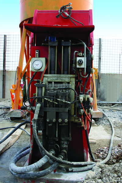
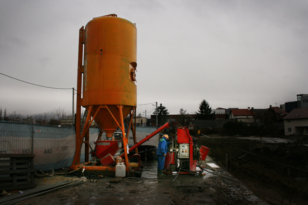
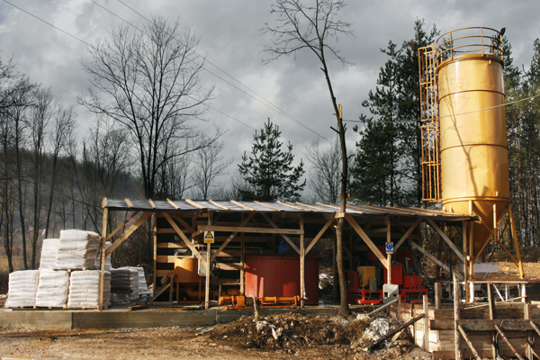
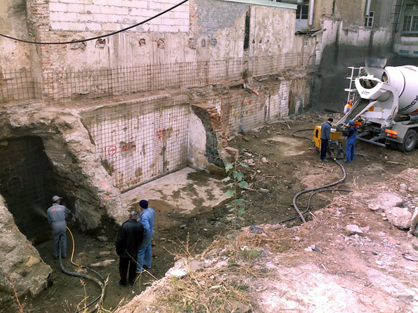
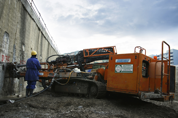
Consolidation grouting includes procedures of filling in voids and cracks in the soil or rocks with mud solutions or with suspensions of various binders and fillers. It is performed by injecting the said mixtures (suspensions and solutions) into previously drilled boreholes in the ground or rock until a certain “pressure grout” is achieved, which increases as the resistance of the flow of suspension through the voids and cracks in the soil and rocks grows. Materials used for grouting soil or rocks are: mixtures of cement, clay or bentonite with sand and water.
Consolidation grouting is applied in order to reduce the deformability of the rock mass and fix the weak and loose rock behind the hydrotechnical tunnel’s lining. This is performed to prevent the opening of tensile cracks in the concrete of the linings of new tunnels. In already built hydrotechnical tunnels, consolidation grouting is carried out to prevent the formation of new cracks and the expansion of existing ones in the concrete lining of the tunnel. Consolidation grouting has the biggest effect on fractured rocks with a small deformation modulus. The bigger the deformation modulus in undisturbed rocks, the smaller the effect of consolidation grouting is. In practice, the deformation modulus of a natural rock can scarcely be increased to more than 8.000 MN/m2.
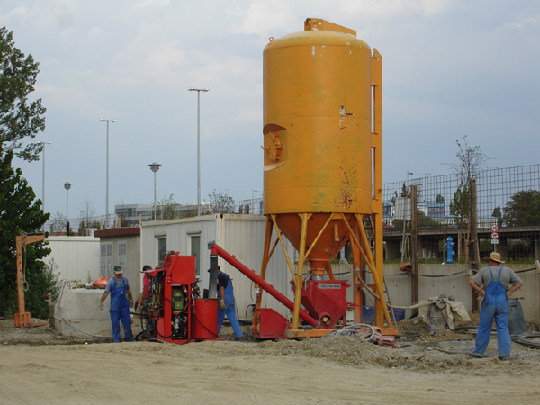
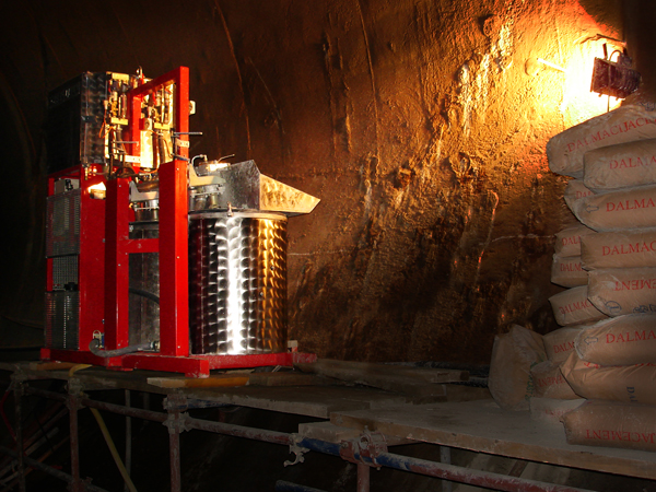
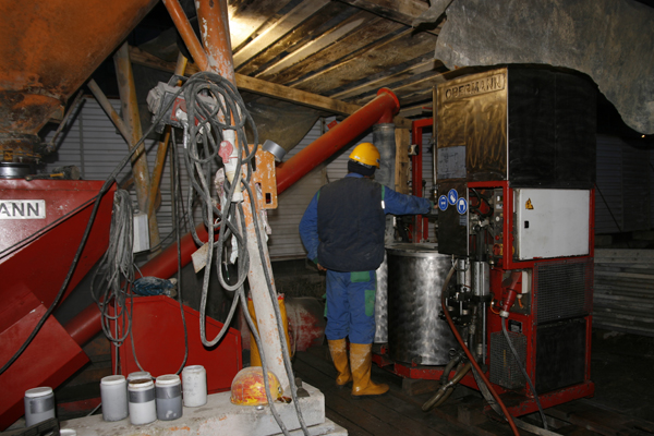
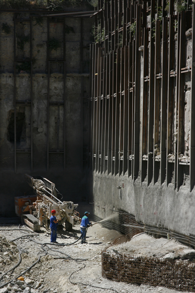
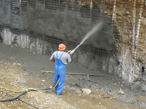
Two methods for installing shotcrete are used these days: dry mix and wet mix. When using the dry mix method, cement and aggregates are dosed in specific and calculated rates. The measurements are carried out by weight. When dosing, the aggregate has to be dried or sufficiently drained to keep the moisture content stable, not over 7%. The cement and aggregates are mechanically mixed with a mixing machine. Shotcrete should be installed up to 90 minutes after it has been mixed. This time frame is even smaller when the temperature and humidity are higher. The mixing time is at least three minutes. The wet mix method only uses liquid types of materials to accelerate bonding. These materials are added to the nozzle or near it. The amount of the materials for the acceleration of bonding is controlled by the accelerator pumps in order it to be proportional to the capacity of the cement pump. The nozzle should be such as to ensure that the accelerator and the wet mix are mixed homogenously.
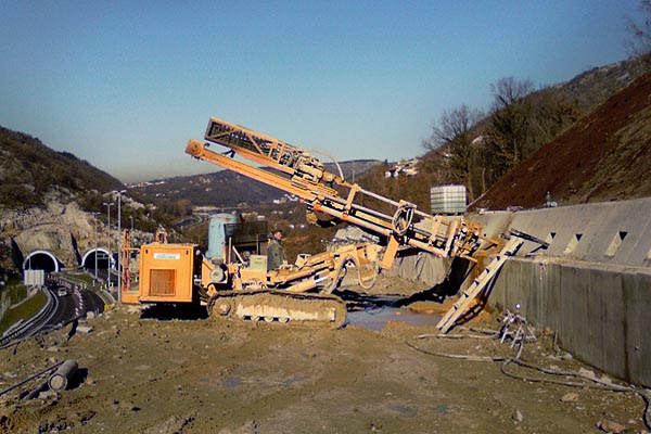
Various effective and economical methods for stabilizing slopes are used nowadays.
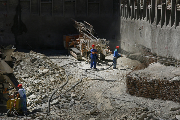
Wire rope nets and shotcrete
A net that prevents small debris falling on the road is used, and over it a protective, 3 to 5 cm wide, layer of shotcrete is installed. This is mainly used in places where it is thought that the debris will be too fragmented to be held by the wire rope nets with weights. The generation of hydrostatic pressure between the rocks and shotcrete has to be avoided, so short drains, 2 meters in length, are installed on a 4x4 meter raster.
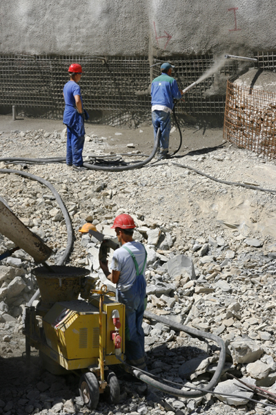
Shotcrete and anchors
It is used in the protection of cut slopes in places where it is expected to find falling unstable blocks disturbing the geometry of the slope. Rock anchors of 3, 6 and 9 meter length are installed. There length depends on the quality and condition of the rock mass, the size of the blocks from the rock mass and the width of the zone needing protection. In zones of extremely crushed and weathered rock masses self-drilling anchors (so-called IBO anchors) are installed, and in the rest of the zones that need protection classical rock anchors are used. Depending on the size of the potential unstable blocks and width of the fault zones, the TIP-4 protection is divided in three subtypes: 1. protecting the slope with 10 cm of shotcrete, rock anchors 25mm in diameter and 3m in length on a 3x3 meter raster, and Q131 reinforcement grids. This type of protection is used in wider fault zones to tighten unstable blocks; 2. protecting the slope with 10 cm of shotcrete, rock anchors 25mm in diameter and 6m in length on a 3x3 meter raster, and a Q131 reinforcement grids. This type of protection is used in extremely wide fault zones to tighten unstable blocks; 3. protecting the slope with 15cm of shotcrete, rock anchors 32mm in diameter and 9m in length on a 3x3 meter raster, and a Q131 reinforcement grids. Possibly use Q131 reinforcement grids if necessary. This type of protection is used on soils with exceptionally poor quality.
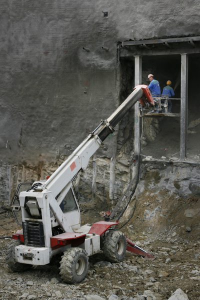
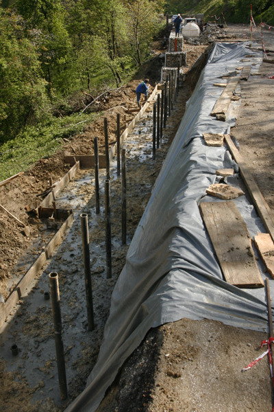
Protecting slopes with gabion retaining walls
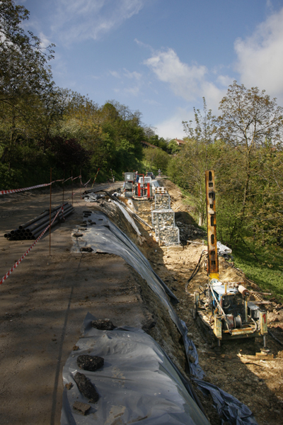
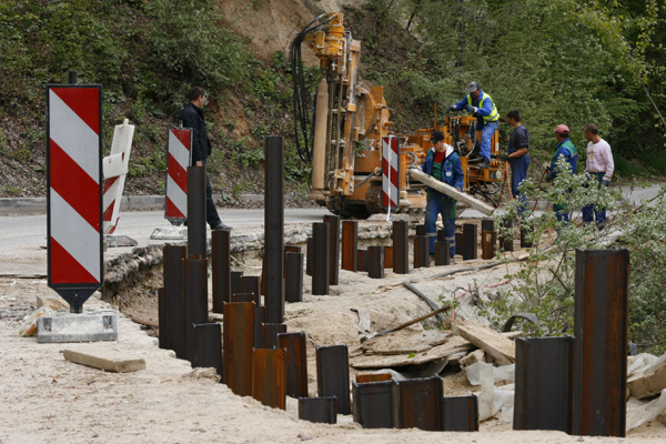
One of many effective methods of repairing and protecting slopes is the construction of gabion retaining walls. These walls are foldable metal constructions made of hexagonal wire mesh filled with cuboid or cylinder stone material. Due to its advantages, the gabion wall is widely and variously applied. We often use them when repairing nicks and notches, or during the renovation and restoration of roads in places where usual expansion is not possible. Expansions are then done by nicking and notching the slopes above and below the road, on which occasion HEA steel sections at an approximate distance of 0,8m are drilled, installed and injected along with steel pipes which are calibrated and built-in in two rows the distance between which is one meter. Concrete foundations with approximately 0,3 thickness and width of 1,5 to 2,4 meters are built at the installation locations of the HEA profiles and steel pipes. Together with the wire mesh and rock material they form gabion retaining walls built in multiple rows with different heights and thicknesses. Designed as such assemblies, they are used exclusively for stabilizing slopes and roads and their drainage on their construction sites. Due to its good characteristics and many advantages over other types of structures, as construction elements gabions can, in many cases, successfully replace the massive concrete structures.
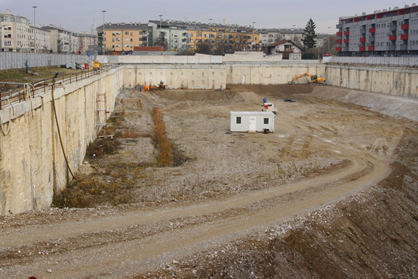
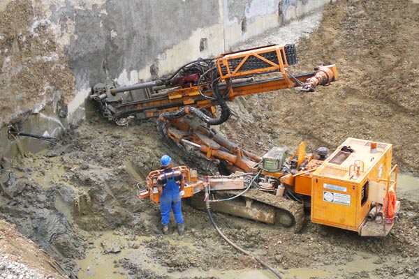
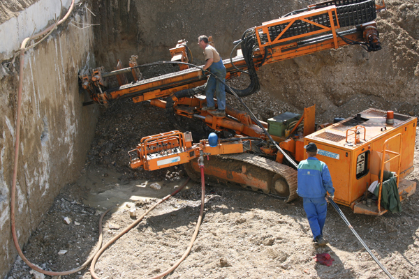
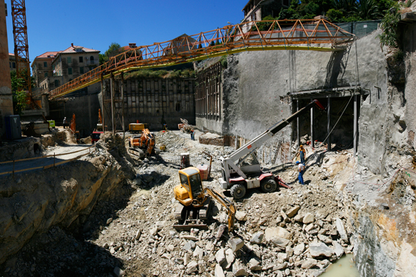
Construction pits for objects which include underground floors on several levels. The depth of the pits is usually up to 30 meters. Prior to the excavation, one or two trial pits are dug in order to get soil parameters according to which the object is designed. The construction pit is usually protected with a temporary wall of reinforced concrete, called the diaphragm, typically 50 to 80 cm thick. If investors seek greater space-saving, 40 to 50 cm walls made of incised piles are used. Both the diaphragms and the piles are additionally secured by ground anchors of up to 1000 kN capacity. They are installed in several rows, depending on the depth of the construction pit. Hammered IPN steel profiles and steel planks (Larsen-planks) are used for securing shallower pits.
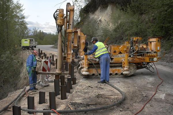
Micropiles
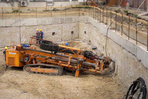
Micropiles are sometimes used as elements of the protective structure of construction pits. They are columns of reinforced concrete, up to 380mm in diameter and of various depths (up to 20,0m). Most frequently they are used to transfer the weight from the building into the deeper, well bearing layers of soil. In these construction elements, the length is substantially greater than the cross-section. As load-bearing elements they can act individually or in a group, connected by a reinforced frame and subjected to pressure or traction. They can be made as reinforced concrete or steel sections. Micropiles of reinforced concrete are often made as boreholes of a particular profile into which rebars are installed. After the installation, the rebars are filled with predetermined brand of concrete using the contractor method. Perforated steel tubes of different diameters are often used when repairing a road, which are then installed in the previously drilled boreholes of a particular profile. After installing these tubes, the boreholes are usually grouted under certain pressure with a cement suspension.
It is performed on low quality soils, regardless of the building category, with one or two trial pits. Loss of the soil stability is caused by many human activities, such as removing vegetation, cutting ground for construction work, adding loads to slopes, and because of unfavourable natural occurrences like earthquakes, erosion, water flow, temperature changes and frost. Investigations can be designed for foundations, which can be shallow or deep, rehabilitation of landslides, which can be active or potential, sizing slopes, nicks and notches, sizing supporting structures, borrow pits, etc.
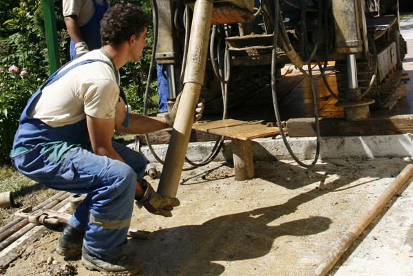
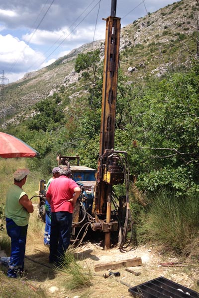
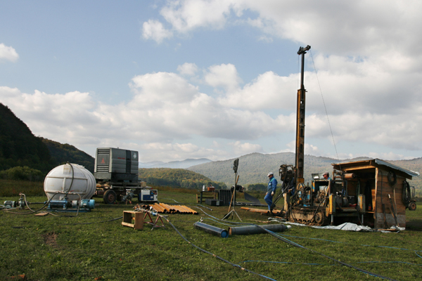
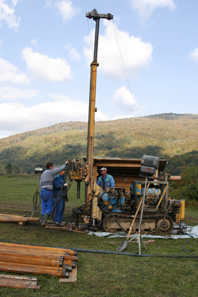
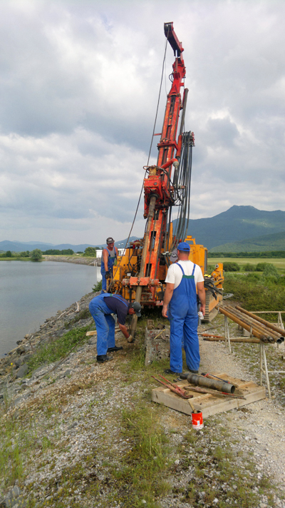
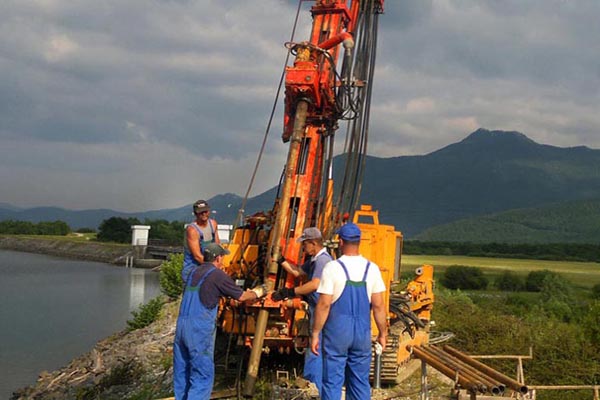
Geotechnical investigations are expensive, but not visible. Therefore, investors are always trying to reduce them which can be fatal later on, during the designing, constructing and using the building. The purpose of the geotechnical drilling is extracting the core for further processing. In principle, they are divided into two groups:
Geomechanical test drilling with continuous core drilling of soil and rock and Hydrogeological test drilling with continuous core drilling of soil and rock together with the installation of exploitation or observation tubes (so-called piezometers). They are used to obtain the arrangement of soil layers by depth. During these investigations every change in material is noted and its properties, which do not require complex laboratory test, are described. Identification tests are used, as well as detailed descriptions of what could be found during the excavation and drilling. The occurrence of groundwater is noted.
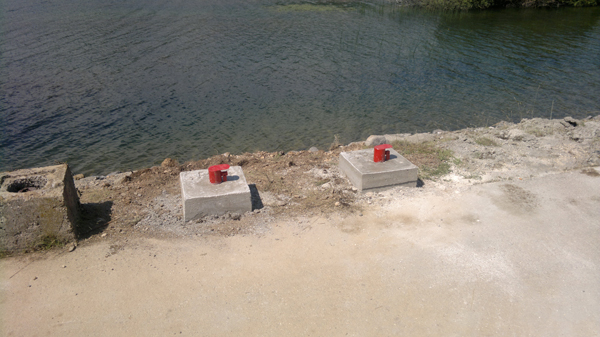
Every coated borehole can, in case its bottom reaches the aquifer, be used for observing the changes in groundwater levels. If aquifers appear in layers of soil between impermeable materials, piezometers can be installed into those layers. Piezometers are devices that allow long-term measurements of groundwater levels or the pressure in the aquifer layers and their change over time. They are installed in boreholes in such a way as to have a connection with the surface. It can be done via tubes, and nowadays increasingly through electronics. The perforated tube part is installed in the borehole at the point of the layer where the measurement of water pressure is done. The tube is sealed by expanded clay both above and below the measuring level. A filter connected with the surface of the area is installed in the perforated part. It is necessary to build a protection for the entrance of the piezometer in the field so observations could be done according to a specified program. Piezometers can measure sub-artesian and artesian groundwater pressure.
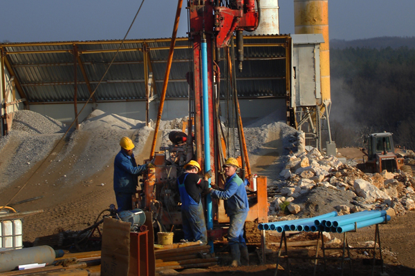
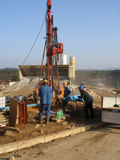
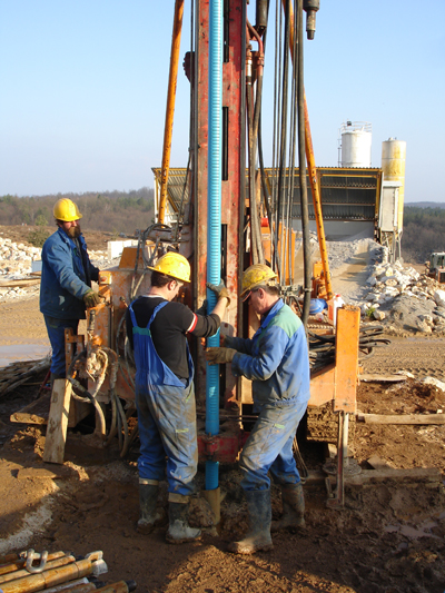
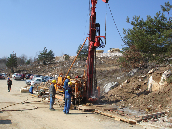
The well is a vertical hydrogeological object used for extracting groundwater or for direct testing and monitoring groundwater regimes. Each well is a whole by itself and differs from others in depth, capacity and water quality. Geotehnika-Konsolidacija d.o.o. offers you the construction of drilled wells, which are significantly deeper than dug wells. The very depth of the drilling and the application of various drilling methods with specialized tools depend on the geological environment and the amount of water that needs to be extracted.
|


